The iron cylinder

Wheel Wreck: Intro | Cargo mound | Iron cylinder |Remains of the vessel | 3D site plan | Dive video

Engine cylinder fragments

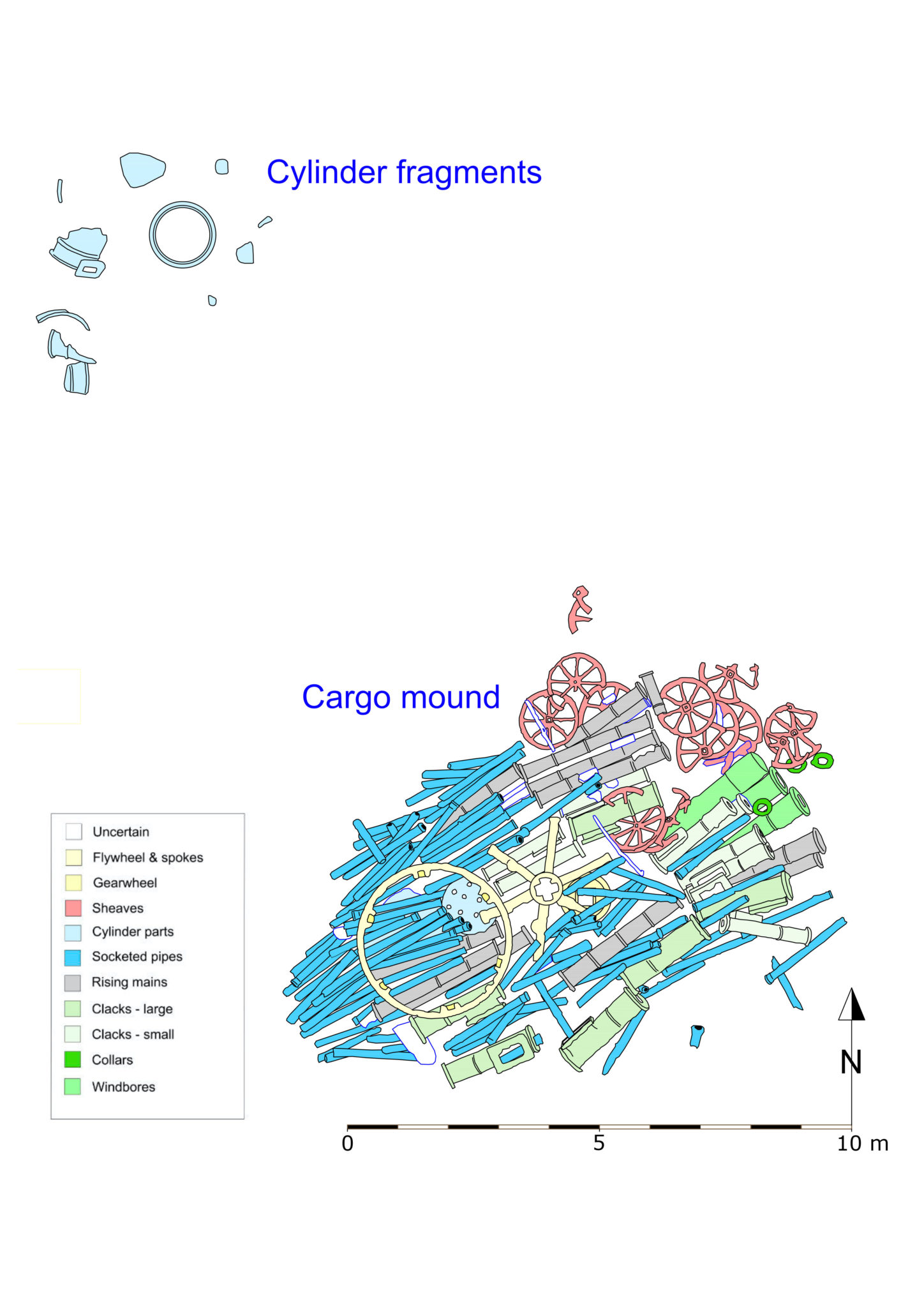
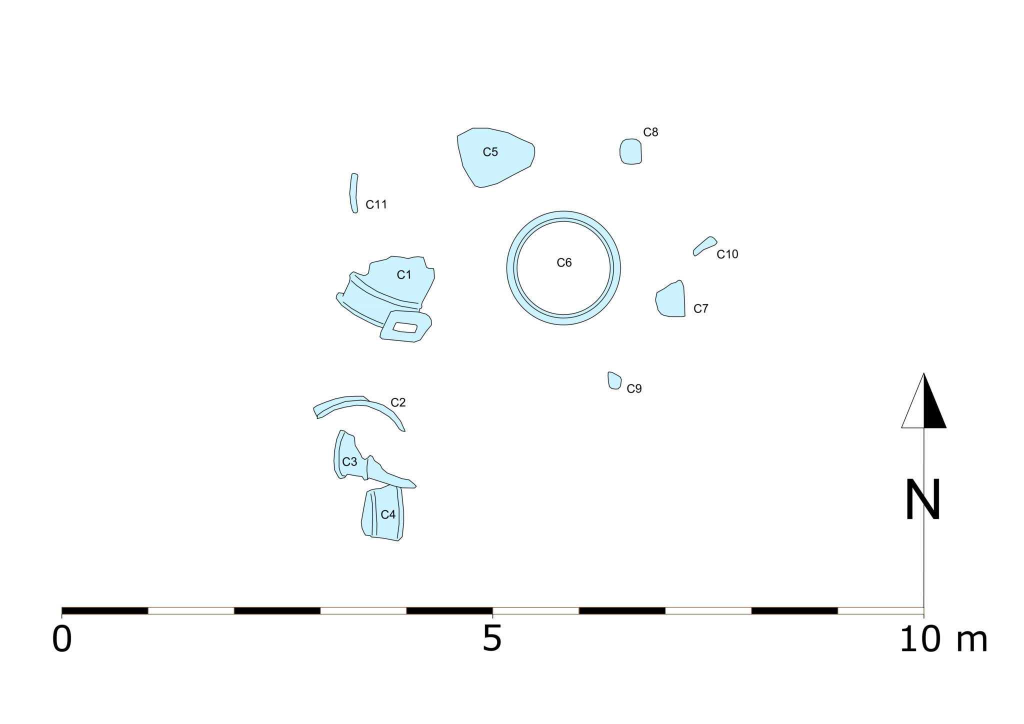
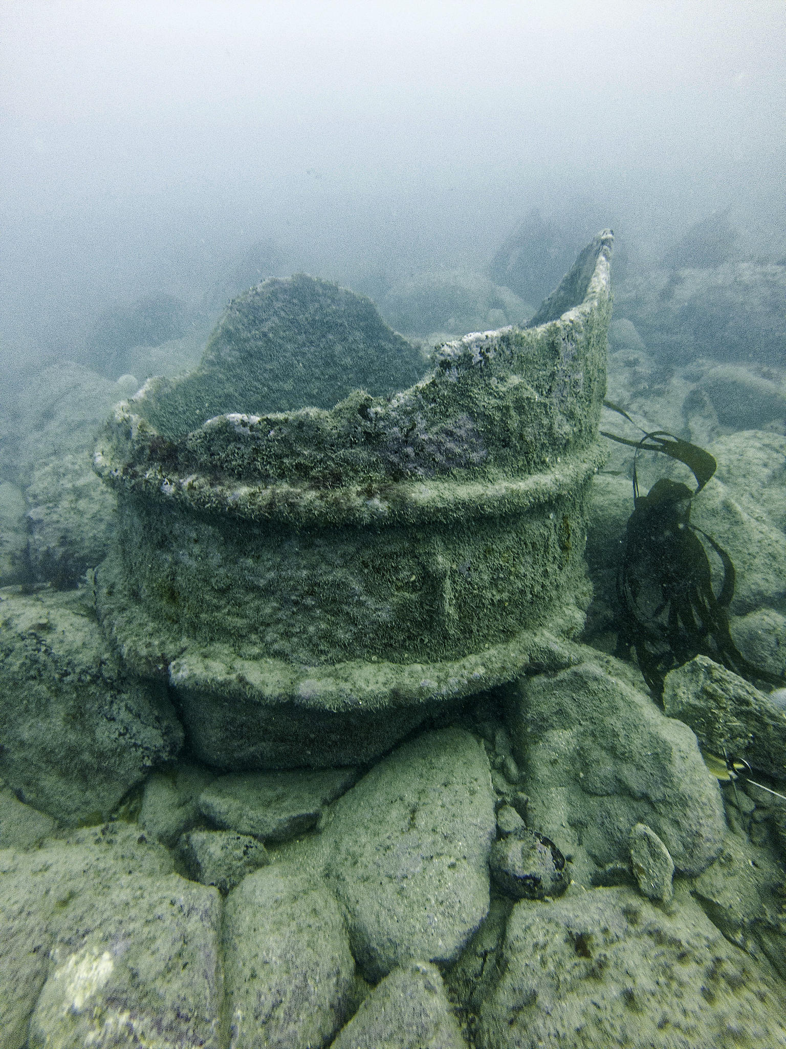
A small group of six iron fragments have been noted some 11m to the north-west of the cargo mound.  These fragments all appear to be the remains of a cast iron cylinder which has been broken into six major pieces and a greater number of smaller fragments. The seabed in this area is composed of large stone boulders, so locating all the smaller fragments was problematic. The area around these six fragments was searched and a further five fragments were identified and surveyed. This brings the total number of fragments located to eleven (C1 – C11).

A 3D model is available at the bottom of this page.

Photo of one of the cylinder fragments underwater. Two ribs can be observed around its circumference and the top is jagged. The object is covered in a furry growth of algae.
The large cast iron cylinder lying upright on the seabed. Note the flange at the bottom and the reinforcing ring on the outside – 0.33m above the flange. The cylinder survives to a height of 0.84m

Plan of the cylinder in relation to the cargo mound

A plan showing the location (about 11 metres north-west) of the cylinder fragments in relation to the cargo mound. Colours indicate the component types on the cargo mound.
Plan showing the location of the cast iron cylinder fragments relative to the cargo mound.

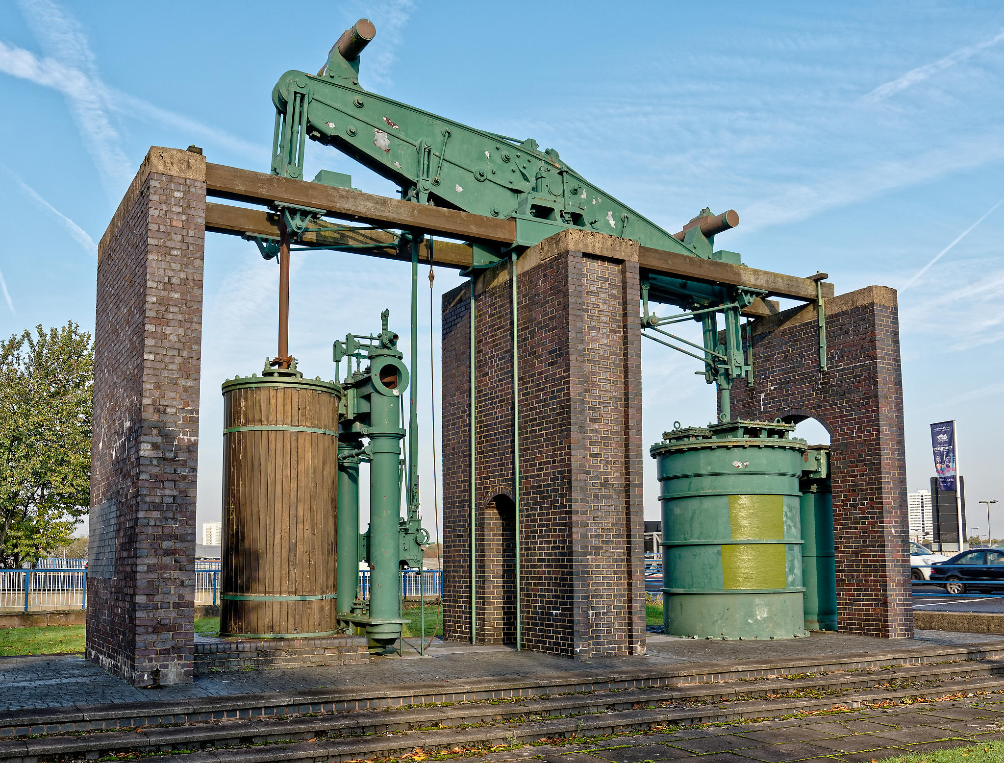
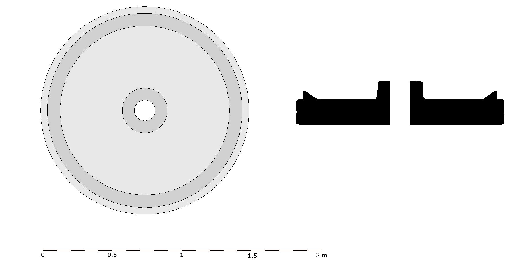
The cylinder has an internal diameter of 1.08m (42.5 inches), and external diameter of 1.16m – the flange with bolt holes has a maximum diameter of 1.32m. This is probably a steam engine cylinder – engine cylinders of this period are usually categorised by their internal diameter in inches. If this is a cylinder from a steam engine, it is probably not from a rotative engine as rotative engine cylinders of this period are usually of smaller diameter than this example. The most likely use for this engine is as a pumping engine for raising water in a mine, waterworks or in a canal system. One further possibility is that it was a ‘blowing engine’; these were used to blow air into a blast furnace. An example of such an engine is the 42 inch Grazebrook blowing engine. The Grazebrook engine survives at Dartmouth Circus in Birmingham and was built by M & W Grazebrook to a Watt design in 1817.

Plan of the eleven cast iron cylinder fragments C1-C11, with a 10 metre scale and north bar. Fragment C6, roughly in the centre of the plan, is circular and shows the whole diameter of the cylinder.
Plan of the eleven cast iron cylinder fragments C1-C11. Only one fragment (C6) shows the whole diameter of the cylinder – and this has a large fracture running vertically down the southern side.
Photograph of the Grazebrook blowing engine built in 1817 against a blue sky. A red brick structure of three supporting walls supports a green iron beam on the central wall. On either side of the central wall is a large cylinder. The left hand cylinder is cased in wood, and is 42 inches in diameter. The Right hand cylinder is painted green and is an 84 inch air pump.
The Grazebrook blowing engine preserved on a traffic island in Birmingham. The engine was built in 1817 and has a 42 inch cylinder (the same diameter as the Wheel Wreck cylinder). The drive cylinder is on the left, cased in wood – the cylindrical object on the right is the 84 inch air pump.

 A small fragment of cast iron cylinder (F111) was recovered for further investigation. When the sample was mounted, sectioned and polished it was possible to establish the true thickness of the cylinder wall, measured at 21mm (7/8 of an inch) in the piece collected.

An underwater photograph of cylinder fragment C6 lying upright on the rocky seabed. The flange at the bottom and one of the reinforcing rings can be seen clearly.
The broken cast iron cylinder (C6) lying upright on the seabed. Note the flange at the bottom and the reinforcing ring on the outside – 0.33m above the flange. The cylinder survives to a height of 0.84m with an internal diameter of 1.08m (42.5 inches)

Reconstruction drawing

A greyscale reconstruction drawing of how the cylinder may have appeared. The image is divided into two columns. The left column shows the side view of the cylinder standing upright as it may have appeared. The right column is split horizontally. On the top is a view of the cylinder from the top, essentially circular but with a rectangular protrusion. The lower half of this column shows the plan view from underneath - a circular shape with regular holes showing where rivets would have been positioned.
A reconstruction drawing of the Wheel Wreck cast iron cylinder. We do not know exactly how tall the cylinder would have been as it is so badly broken – the reconstruction shows a cylinder height of 8 feet (based on similar 42 inch engines). Note the unusual spacing of the external reinforcing bands (these are usually spaced equidistantly).
Photograph of a 33 inch engine cylinder on display in the Science Museum, London. It is painted black, is surrounded by a protective railing, and has a rectangular steam port very similar to that found on the Wheel Wreck cylinder fragment C1.
A 33 inch engine cylinder on display in the Science Museum, London. This engine was known as ‘Old Bess’ and was built by Boulton and Watt in 1777. It was used to pump water to drive a water wheel in their Soho works in Birmingham. Note the rectangular steam port similar to that found on the Wheel Wreck cylinder fragment (C1).

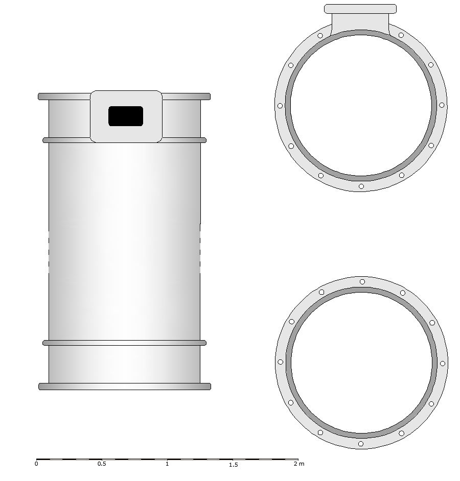
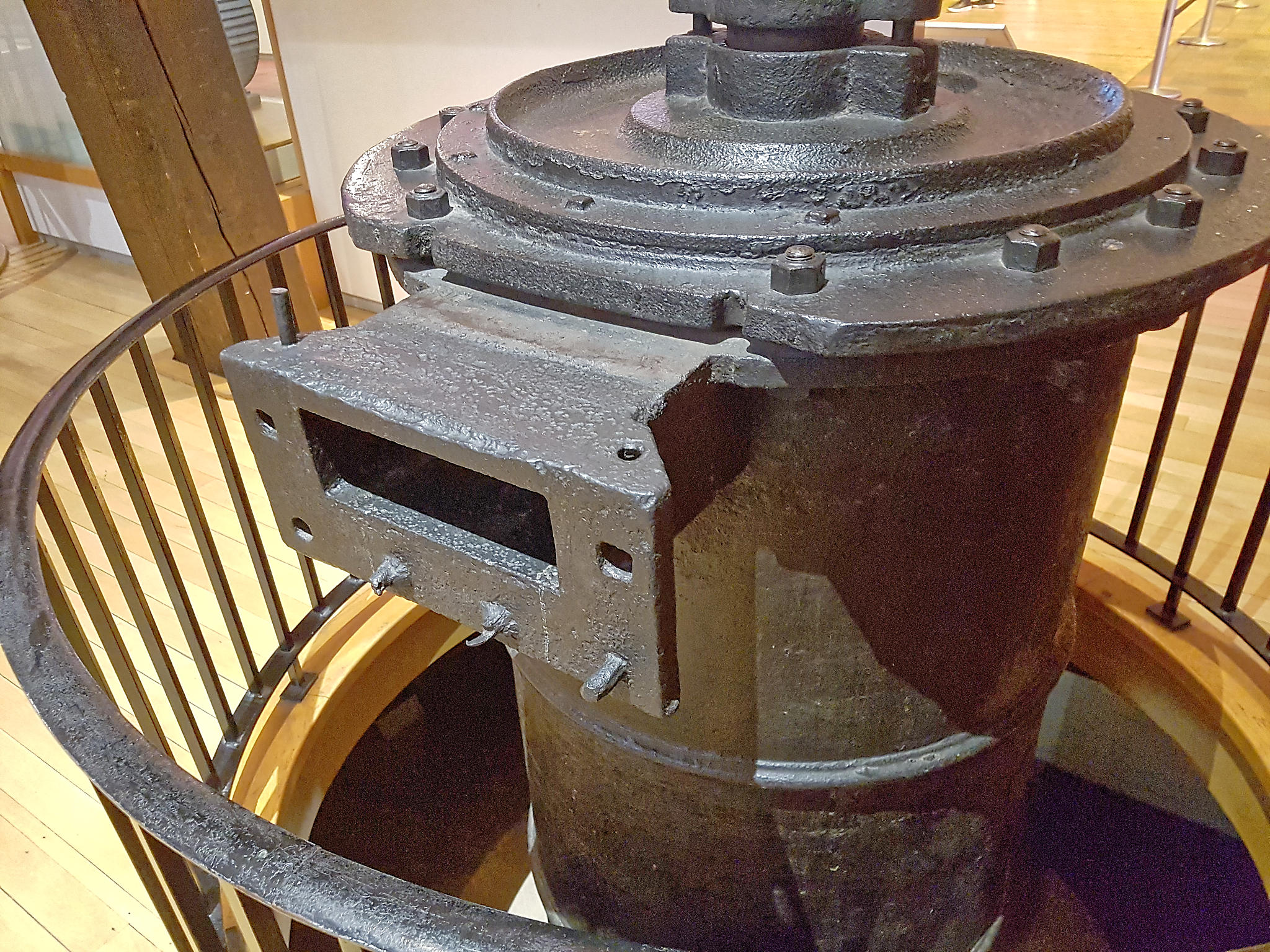
The early Bolton and Watt engine known as ‘Old Bess’ and preserved in the Science Museum London was built in Birmingham in 1777. The engine cylinder has a number of similarities with items discovered on the Wheel Wreck. The steam port appears to be very similar to that surviving in fragment C1 (see reconstruction drawing above). The circular object SW2 discovered in 2018 and tentatively identified as a cylinder cover/head bears an uncanny resemblance to that on ‘Old Bess’.

Reconstruction drawing and section of (SW2) – a small circular iron object partly buried under the cargo mound. A scale is included in the image to indicate its original size of about 1.5m.
Reconstruction drawing and section of (SW2) – a small circular iron object partly buried under the cargo mound. Reconstructed from remote video footage.

3D model

Click play to view the 3D model of the iron cylinder fragments. Explore it by using your left mouse button or finger to rotate the model, and your right mouse button or two fingers to pan around it.

Use the menu at the bottom of the 3D viewer to explore more advanced options.