Wheel Wreck: Intro | Cargo mound | Iron cylinder |Remains of the vessel | 3D site plan | Dive video
Cargo Mound: Intro and components list | Explore the cargo | 3D model
Identification of the individual components was undertaken in 2018. The numbering relates to components marked on the 3D cargo mound.
1-5: Wheels
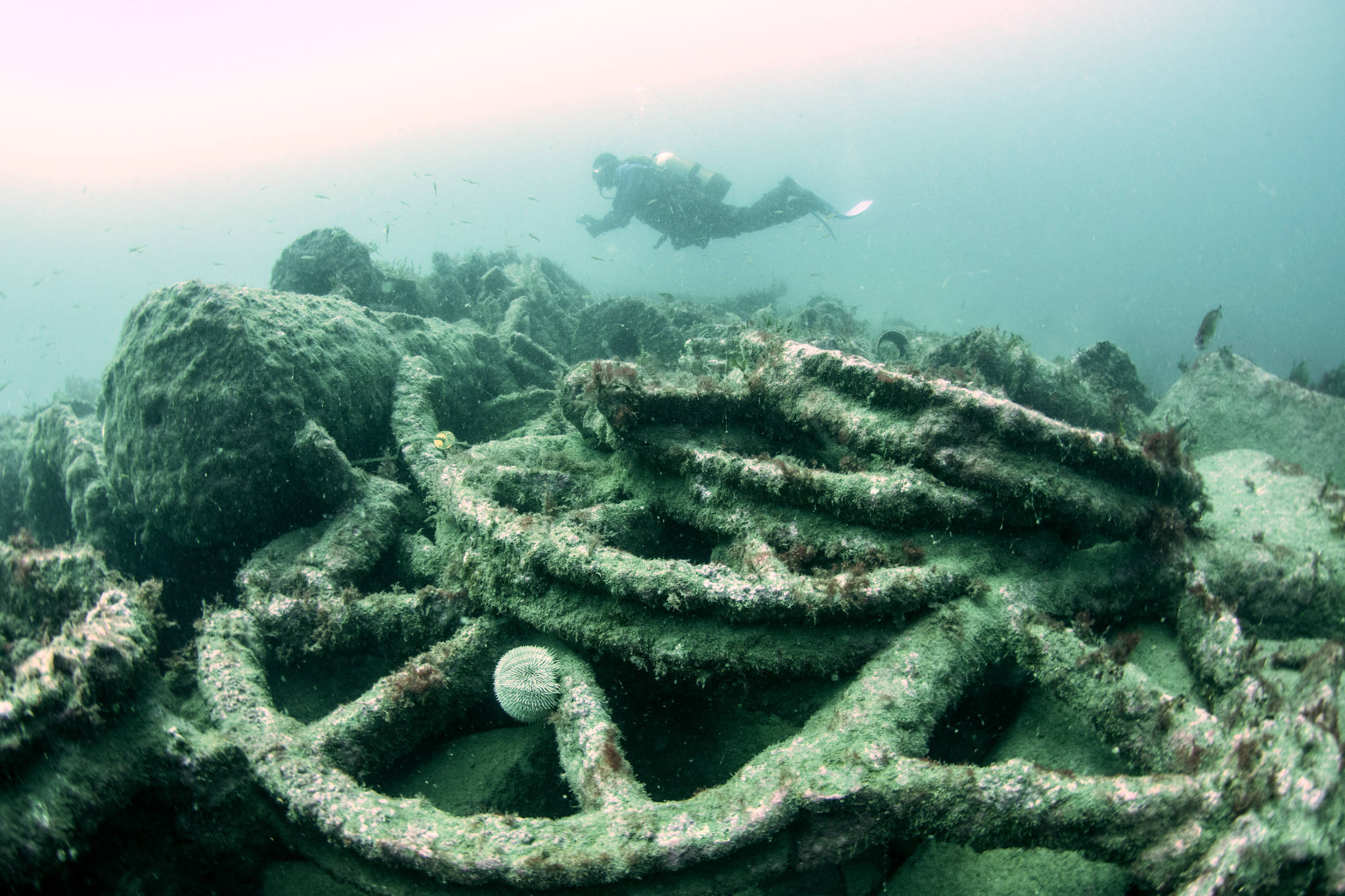
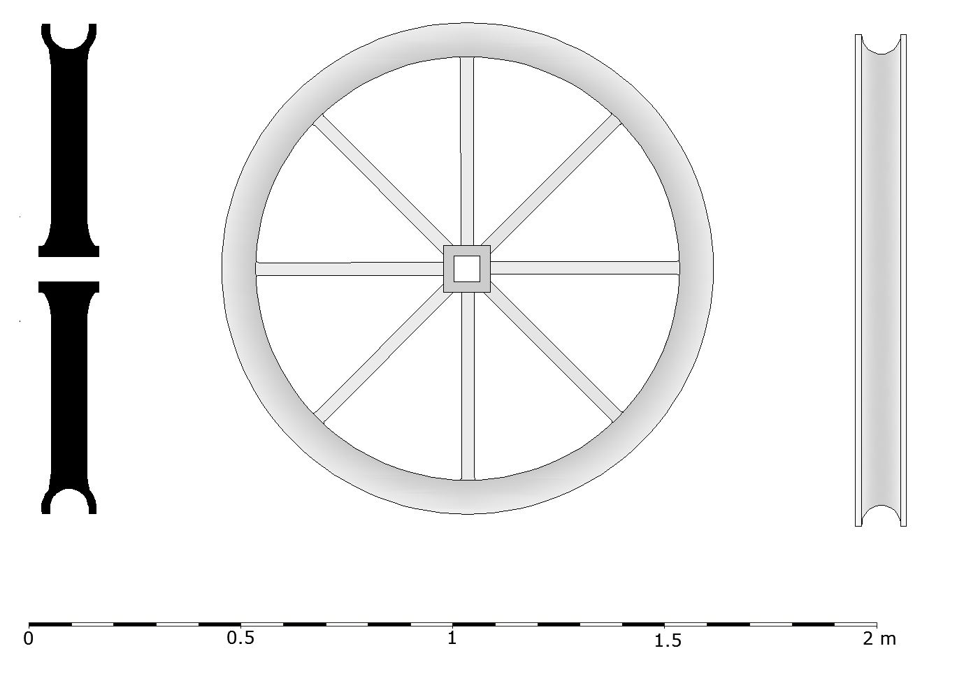
The most striking feature of the cargo mound are the iron wheels from which the wreck was named. At least three different types of wheel have been identified. The majority of the wheels are eight-spoked cast iron sheave wheels with a square hub. These are all about 1.16m (3.8ft) in diameter with a groove in the outer rim to accommodate a rope or rod. There are 12 of these wheels; only three are completely intact, with some consisting only of dispersed fragments.
There are a number of functions these sheaves could have fulfilled: the obvious ones being lifting or hauling items by rope, or facilitating a change of direction for pump rods in crooked mine shafts.

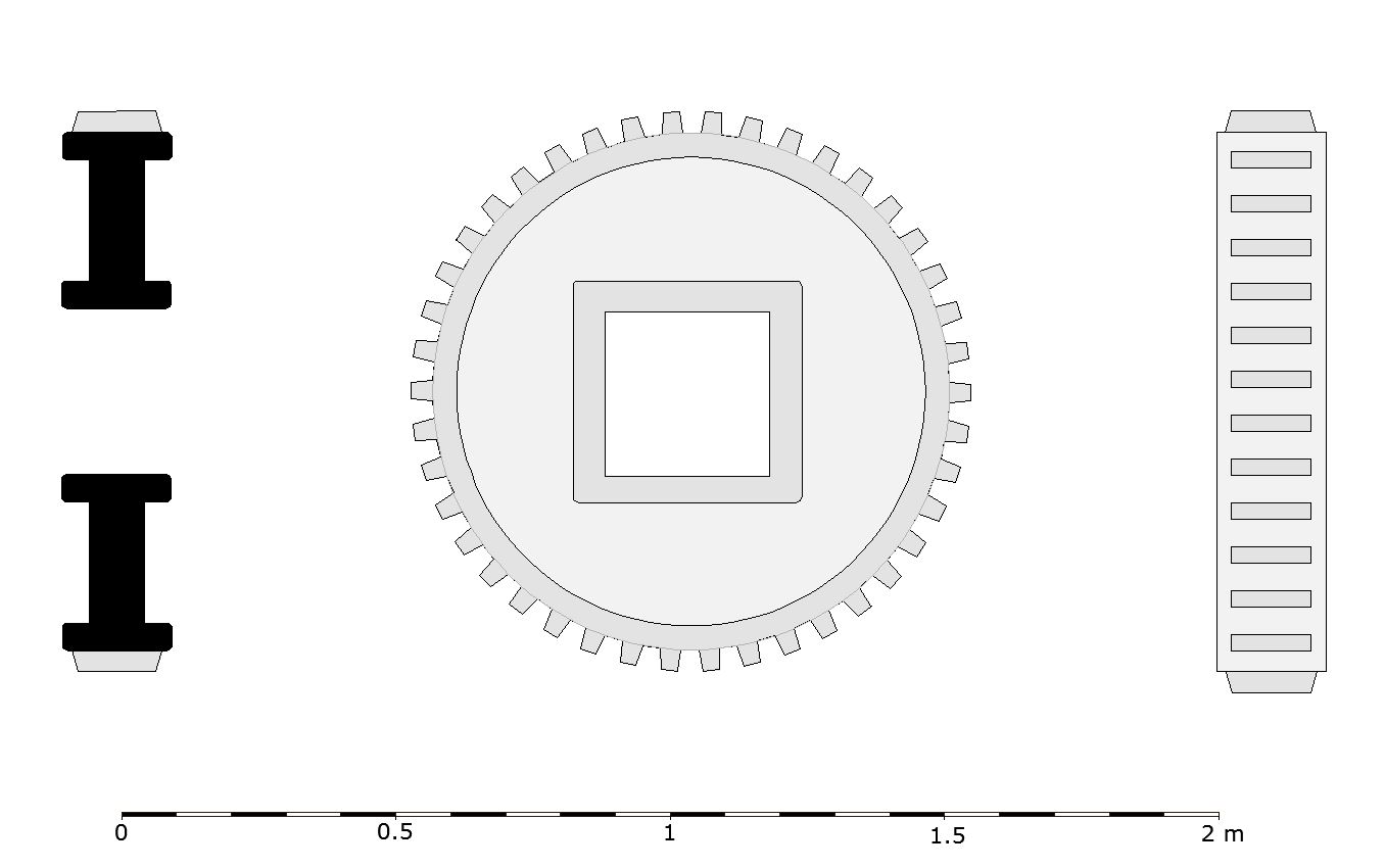
The most impressive feature of the cargo mound is a large iron wheel rim 3.06m in diameter (10ft), 0.19m deep, and 0.15m wide. This has teeth cast into its outer surface, 0.03m wide, 0.15m long, with a space of 0.05m between tooth faces. There are likely to be 126 teeth, and this is likely to be a gear wheel.
Next to this rim sits a set of iron spokes and a hub which appear to have been intended to fit into the six rectangular sockets cast into the inside face of the wheel rim. The reason for manufacturing this wheel in two parts was probably connected with the logistics of transport, as it is estimated that the wheel rim weighed about 1.5 tonnes and the spokes a further 1.25 tonnes, a combined weight of almost 3 tonnes.

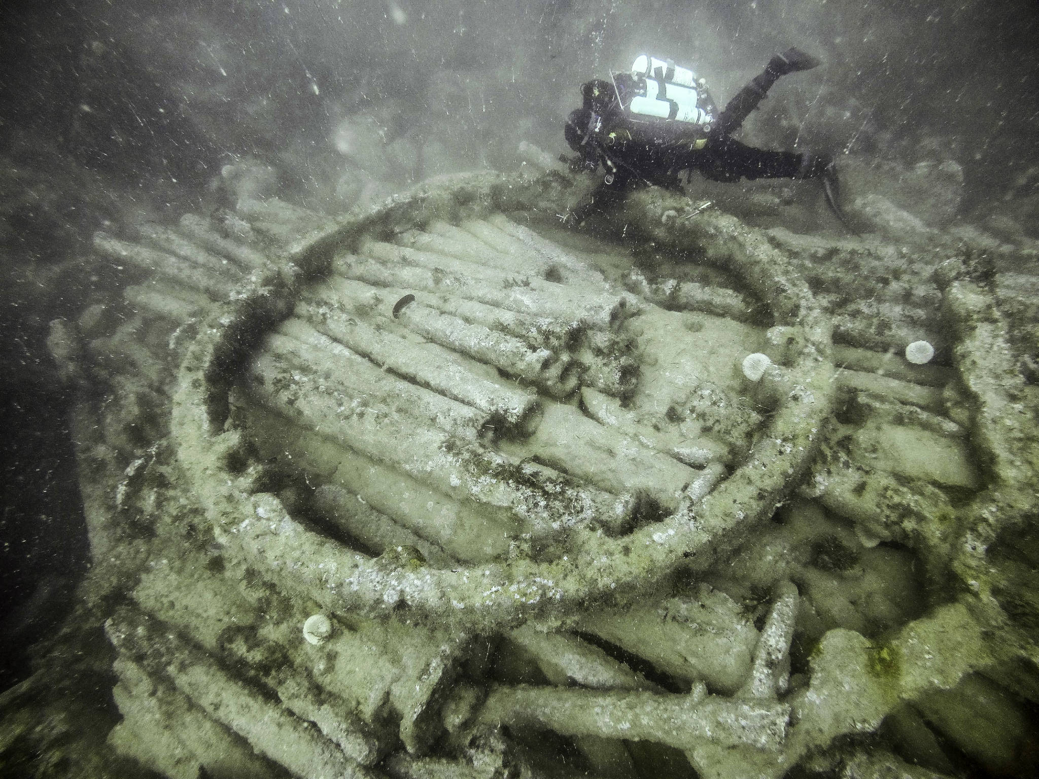


A smaller wheel lies under the spokes of the large toothed wheel and is only just visible. It has a diameter of 1.02m (40 inches) and is 0.2m thick. It has 42 teeth (one third the number present on the larger wheel), and if designed to work as part of a gear train with the larger wheel, the gear ratio would have been 3:1.

Pumping column components
6. Windbore

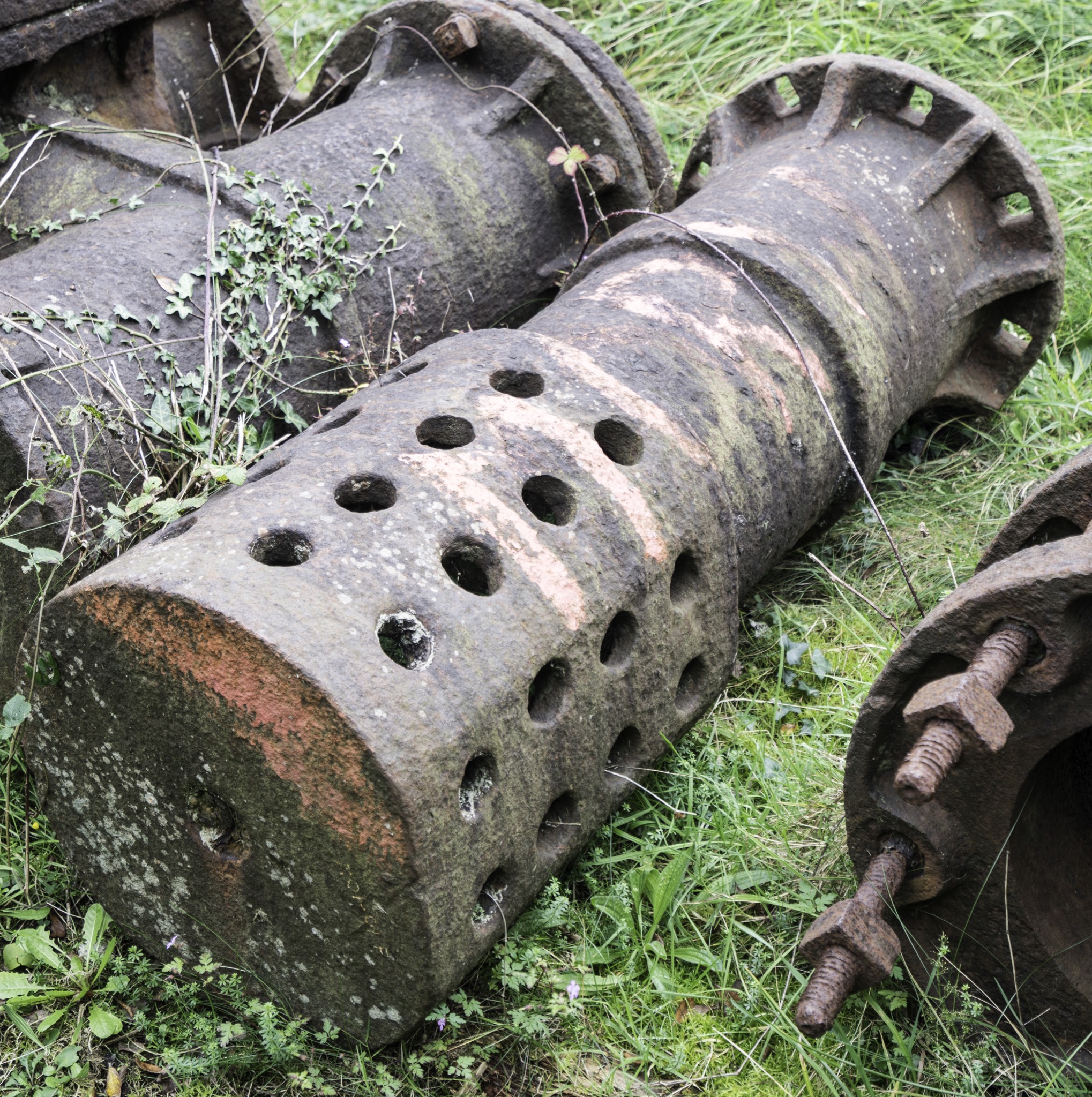
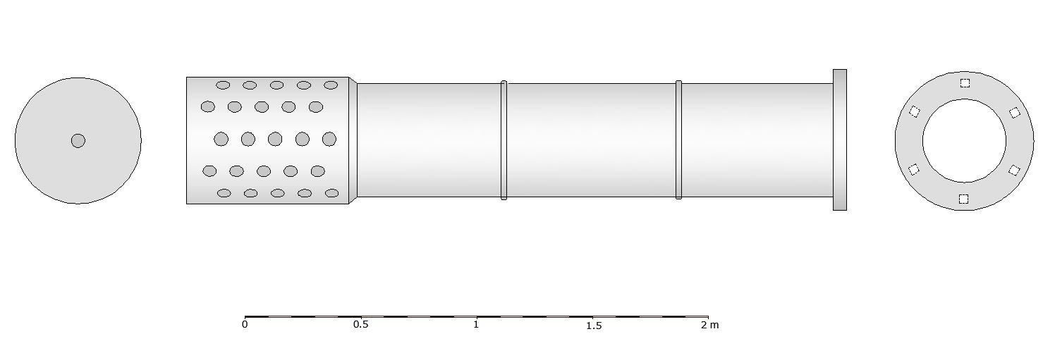
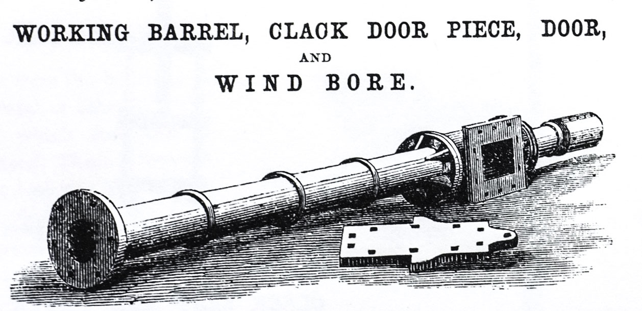
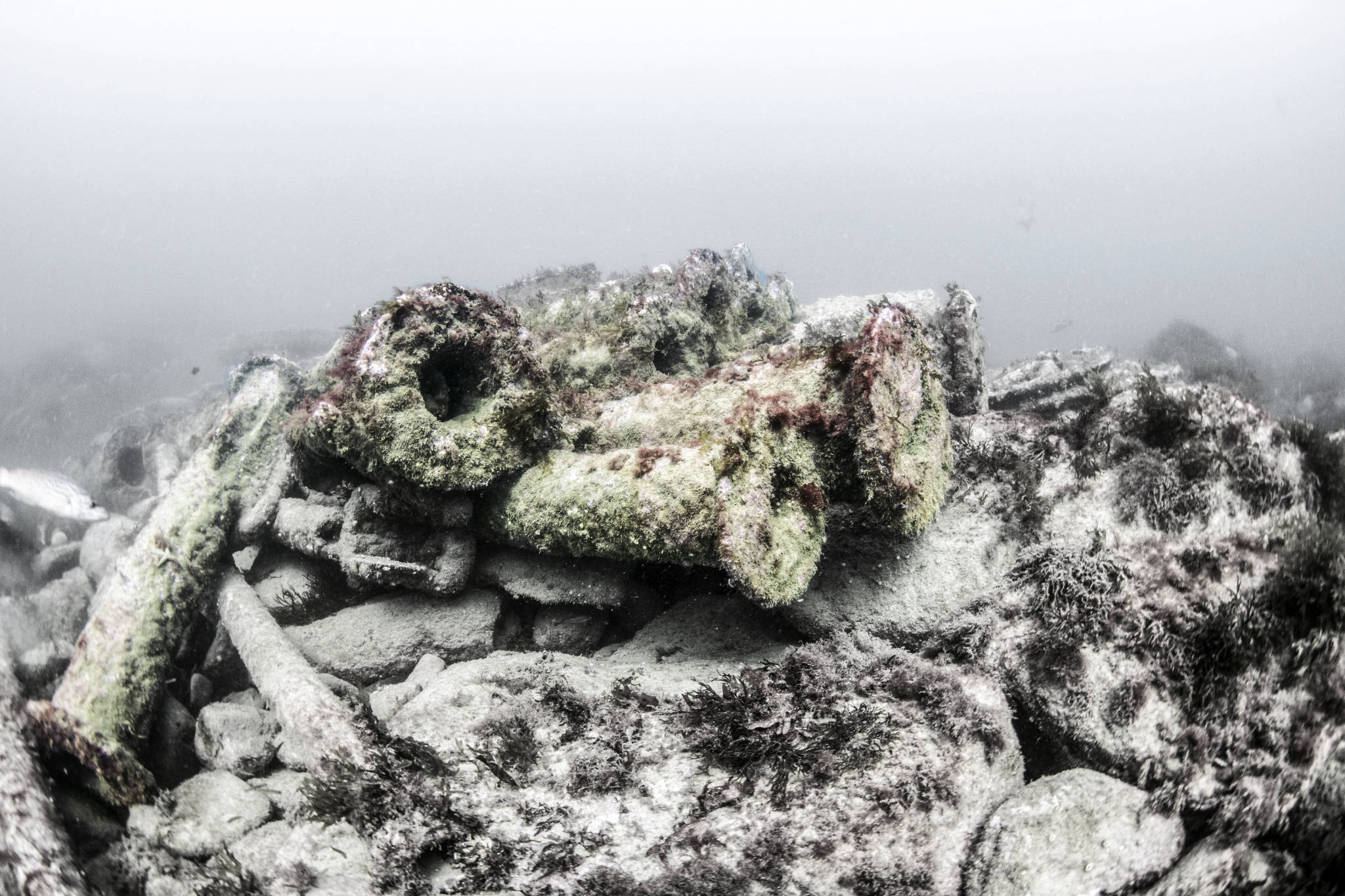
This is the bottom section of the pumping gear. It is an iron cylinder with perforations in the end to prevent stones and debris from being sucked into the pump. This is called a windbore, and the iron pipes it was connected to were called the rising main.
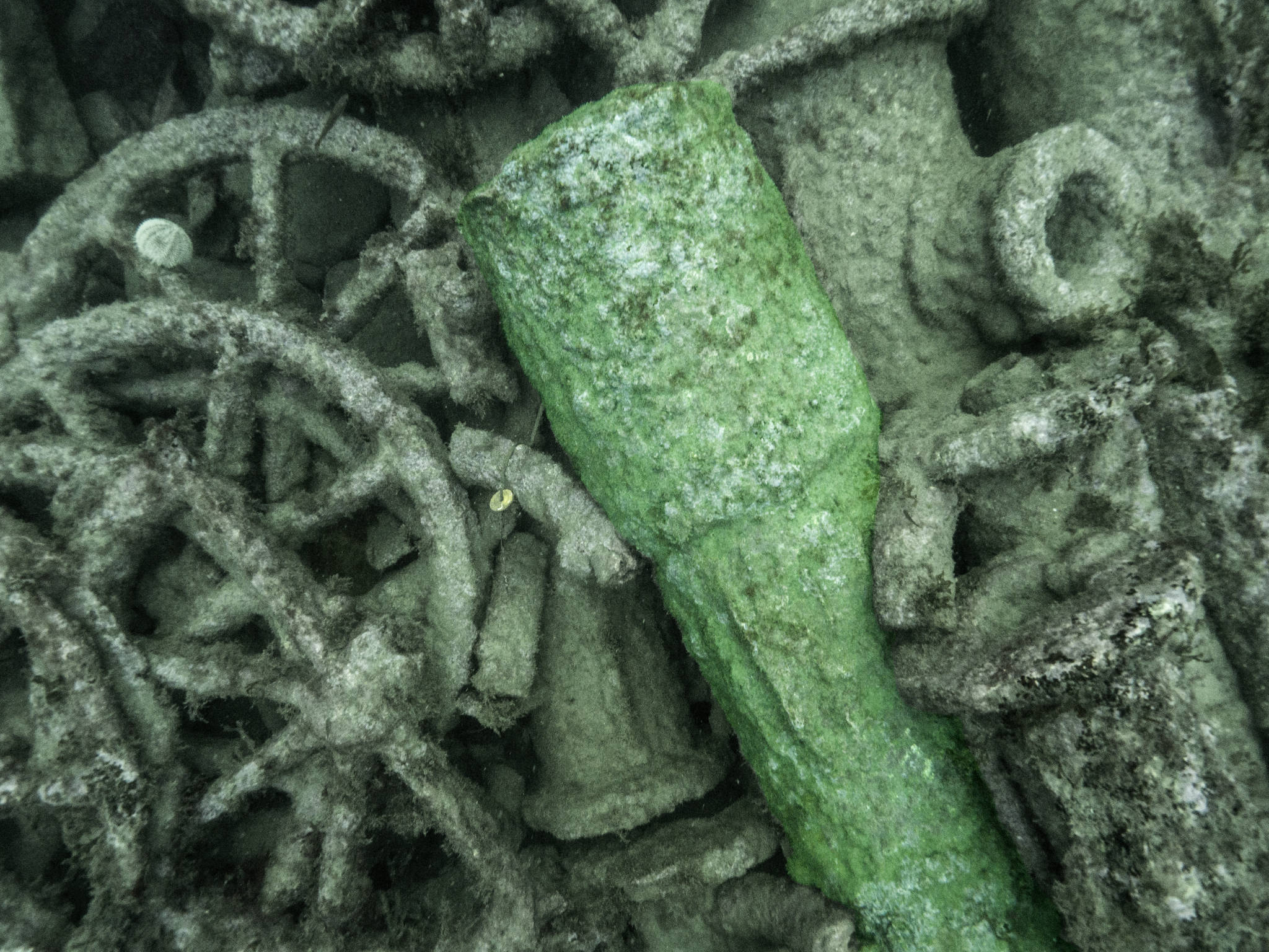
There are three windbores in the cargo mound all stacked next to each other at the eastern end of the cargo mound. The holes in the windbores are largely obscured by the thick layer of iron concretion covering the object. The parallel ridges or fins visible in the centre of the windbore are probably corrosion fins formed as a result of longitudinal cracking of the cast iron, and are thus a post-wrecking feature.
7-11: Clack pieces
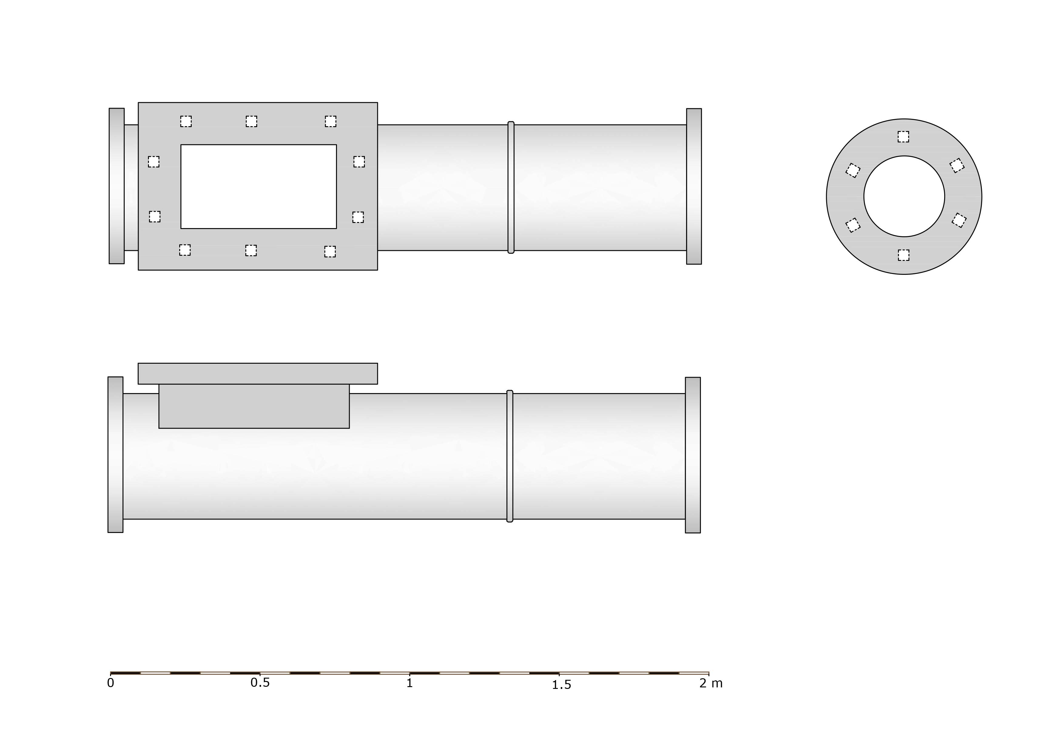
The clack piece (also known as clack valves) is a one-way flow valve incorporated into the pump system to prevent the water from flowing back down the pump pipes (rising main). There was a hinged flap inside the clack valve which closed onto an iron seat, the flap is usually faced with leather to form a watertight seal. They are said to be called clack pieces due to the noise they made as the flap closes. The rectangular opening visible in the photograph is for maintainance of the clack valve – in use it would be covered with an iron door which is missing on this example.


Two different types of clack pieces have been identified. There are six of the larger clack pieces and eight of the smaller type. The larger have flanges 0.51 to 0.55m in diameter with the outer pipe having a diameter of about 0.43m. The smaller have flanges 0.41 to 0.45m in diameter with an outer pipe diameter of about 0.28m. Both types have a single reinforcing band between the clack door and the far flange.

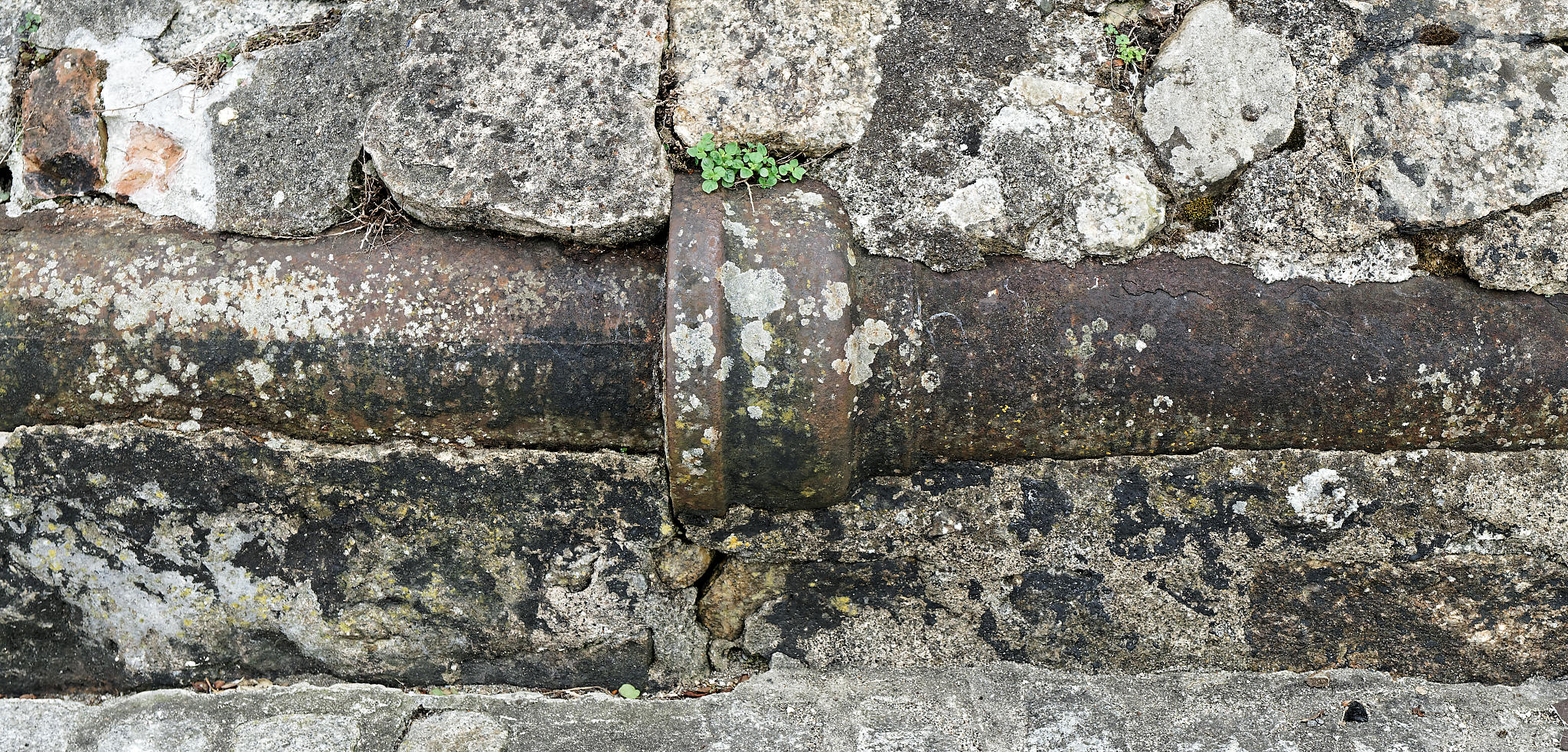
12. Rising main
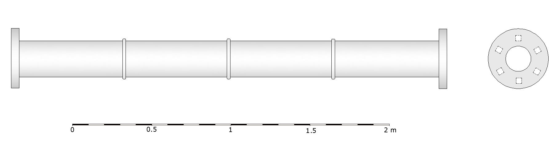
Rising mains are iron flanged pipes used in pumping systems, especially in mines. The term ‘rising main’ is now commonly used but in the nineteenth century these were simply called ‘pumps’ or sometimes ‘pump pipes’.
Thirteen rising mains have been identified on site, and there are probably more concealed within the cargo mound. At least two different diameters of pipe have been observed. The lengths vary between 2.74m (8.98 ft) and 2.77m (9.08 ft).
Rising mains also usually have a number of fillets reinforcing the junction between the outer surface of the pipe and the flanges but none of the rising mains on this site have these fillets. It has not been possible to establish the significance of this absence but it could possibly be a feature related to early pipes or those from a particular foundry. Further work in this area may yield useful results.

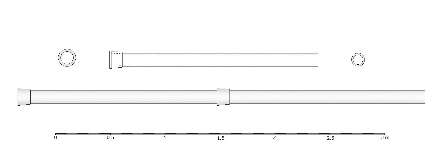
13. Socketed pipes
These pipes are by far the most numerous cargo items present, with about 100 recorded on site – there are probably more in the body of the mound obscured by other items of cargo. The socketed pipes are largely confined to the western end of the cargo mound and are stacked in parallel rows at least three layers deep.

These pipes are 1.95m long, with an external diameter of 0.12m and an internal diameter of 0.10m. They have a socket at one end (0.11 long, external diameter 0.16, internal 0.13) which is large enough to accept the un-socketed end of the next pipe with a small gap.
These pipes were probably intended to convey water at low pressure – such as those employed in gravity-driven drainage systems.
14. Iron collars
It was not possible to determine the function of these three items. They are short lengths of cast iron pipe with a wider ring at one end (possibly a flange). They are heavily concreted which precludes any determination of their exact form. They are 0.38m in diameter at the widest point and about 0.275m long. Their close proximity to the three windbores and numerical equivalence perhaps suggests an association with the windbores?

Archaeological report
The full Wheel Wreck report is available from CISMAS (PDF, 12.4MB).